Quick Start Guide v.1.2
Installation
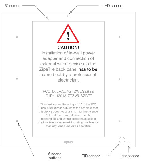
Thank you for purchasing ZipaTile. ZipaTile is the complete home control and automation system in a form of a single device. It can be easily mounted on any wall, in any home. Featuring large number of built-in sensors and hardware modules, ZipaTile replaces numerous home devices such as security system, thermostat, automation controller, IP camera, alarm siren or intercom and brings them all together in one smart and beautiful device.
INSTALLATION REQUIREMENTS: Wireless WiFi Router with connection to the Internet (not included in packaging)
Installation option A:
Available wall socket 100-230VAC 50/60Hz close to the postion of ZipaTile
Installation option B:
In-wall box with mains power available close to the position of ZipaTile
Packaging content:
- ZipaTile
- ZipaTile wall holder (already attached to the ZipaTile)
- Quick installation guide
- AC/DC power supply with adapter plugs
- Wall mounting kit
- Four screws and screw anchors
- In-wall adapter
Optional tools needed:
- Screwdrivers: Flathead and Philips
- Pliers
- Wire stripper
- Non-contact voltage detector
- Wire cutter
- Electrical tape
- Drill and drill bits appropriate for the wall type
Mounting
Table top
ZipaTile is primarily intended for on-wall mounting, but it can be used on table top as well. In this case, please keep the wall holder affixed to ZipaTile and use the built-in table top stand at the back of the wall holder. Just plug AC/DC adapter into free electrical socket and other side into the ZipaTile.
ZipaTile is made for on-wall usage. Table top stand may not be suitable for permanent usage since it can’t resist strong touch pressure.
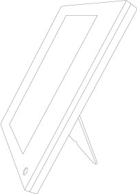
Figure 2. Zipatile build-in table top stand
Wall mount with plug-in power supply
If there is no in-wall box at desired mounting location, please use the wire channel at the back of the wall holder to place the power wires behind the ZipaTile and use the bundled plug-in power supply to connect to the wall socket.
Use safety goggles and gloves when drilling holes in the wall for screw anchors. This product should not be plugged in sockets that can be turned off with a switch.
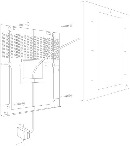
Figure 3. Wall mount with plug-in power supply
Wall mount with build-in power supply
For compact wall mounting into an in-wall box, clip on wire adapter onto the power supply and connect the adapter wires to the AC wires.
 Risk of Electrical Shock
Before performing any electrical work turn OFF the power to the AC wires leading into in-wall box at the main power source. Before starting installation make sure the power is really off by using a non-contact voltage detector.
CAUTION! Installations should be performed in accordance with all national and local electrical codes. If you are unsure or have questions about the installation, please seek an advice of a qualied electrician. Do not apply power to the ZipaTile before completing installation. Please make sure that a proper power cut-off device is part of your power supply circuit (electrical fuse).
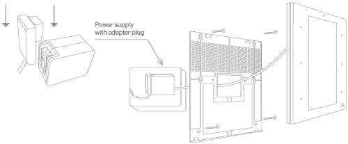
Figure 4. Wall mount with build-in power supply
In addition to range of wireless technologies ZipaTile also offers connection to wired equipment at the back of the device. This includes external temperature sensor (not included), one input and two outputs or three outputs (depending on version) for controlling relays (please note max. voltage and current) or for signaling to boilers, heating or irrigation equipment.
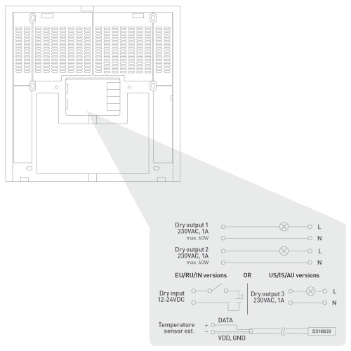
Figure 5. Back of Zipatile
Risk of Electrical Shock
Turn OFF the power to the AC wires leading into in-wall box at the main power source. Use a non-contact voltage detector to ensure that there is no power to any wires in the wall box before proceeding.
Setting up your Zipatile
Turning on the Zipatile
Press and hold (3 sec) the power button on top of the ZipaTile. Boot process will start with the logo on the screen and it will finish when you see the ZipaTile lock screen.

Figure 6. Lock screen
To unlock the device, just swipe up from bottom of your screen.
Wi-Fi Internet connection
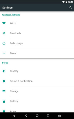
Figure 7. Settings screen
In order to configure your ZipaTile properly, ZipaTile has to be connected to Internet over the Wi-Fi. If you have Wi-Fi network follow these steps:
- Open the Settings app.
- Choose Wi-Fi to view a list of available Wi-Fi networks
- Choose a wireless network from the list
- If prompted, type the network password (touch the Show Password checkbox so that you can see what you’re typing)
- Press the Connect button. The network is connected immediately. If not, try the password again.
Some wireless networks do not broadcast their names (SSID). In that case, select three dots in the upper right corner and choose Add network from dropdown menu. To make the connection, type the network name (SSID) and follow the above procedure from step 4. When setup completes, Wi-Fi Connected icon appears.
It is very important to upgrade applications to the latest version with App Repo application before proceeding.
Zipato registration
At the home page, start ZIPATO application and select REGISTER.
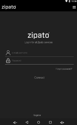
Figure 8. Login screen
When doing this for the first time, you will be required to enter your mobile number and choose your location. This is needed to receive phone and SMS security alerts, as well as to get the local weather information on your ZipaTile. You will need to confirm registration in e-mail that you recieved durring this process. Now you can login to Zipato application.
Once registered and logged in to the Zipato application, ZipaTile will automatically configure itself and you will be able to see the thermostat, security and weather information on the home screen.
If you want to unregister yourself and restart the ZipaTile to factory default settings, go to ZIPATO APPLICATION > SETTINGS > MASTER RESET
ZipaTile self-configure process may cause lack of certain information within a first 10-20 minutes of using ZipaTile.
For more information check out the users manual behind this icon within ZipaTile apps:
![]()
Figure 9. Zipatile manual icon
Having trouble installing your ZipaTile?
Contact Zipato support at: support@zipato.com
Manufacturer / Importer for Croatia:
Tri plus grupa d.o.o
Banjavciceva 11
10000 Zagreb
Croatia
FCC ID: 2AAU7-ZTZWUSZBEE
IC ID: 11391A-ZTZWUSZBEE
This device complies with part 15 of the FCC Rules. Operation is subject to the condition that this device does not cause harmful interference (1) this device may not cause harmful interference, and (2) this device must accept any interference received, including interference that may cause undesired operation.